5G Beam Steerable Antenna Array
New technologies such as full duplex, massive MIMO (multiple input multiple output), and use of millimeter waves (mm-wave) are forming the backbone of 5G. Regarding mm-wave spectrum, to overcome significant free space path loss, atmospheric attenuation, and blockage by foliage at high frequencies; high gain and beam steerable antenna arrays are necessary both on the mobile and base station sides. Beam steerable antenna systems are one of the the key technologies to tackle the challenges in mm-wave bands. Adaptive array systems can maximize their main lobe and minimize interference and hence can be used in base stations. On the other hand, switched beam systems are fed by a beamformer which requires a smaller number of transceivers, resulting in reduced system complexity which can be used on the mobile station.
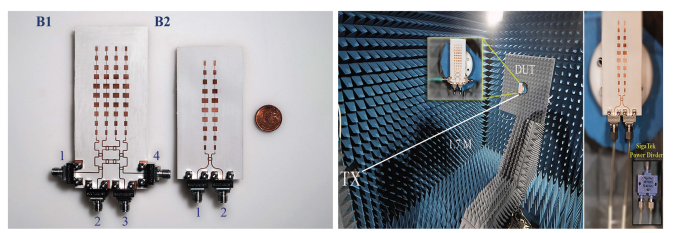
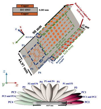
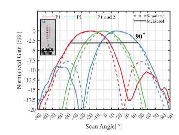
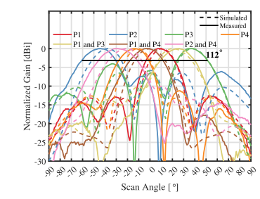
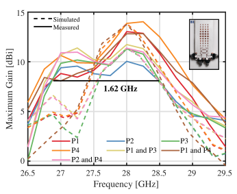
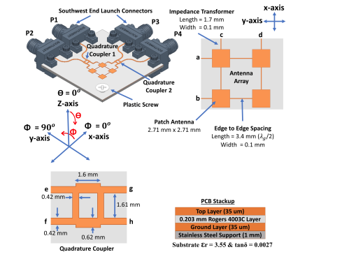
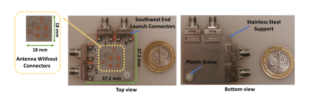
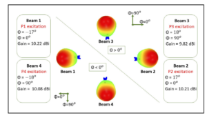
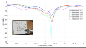
In this project, a novel 2×2 microstrip patch antenna array that can generate 10 switched beams in different directions were designed, manufactured and measured at 30GHz 5G frequency band. In a conventional switched beam system, given a 4 microstrip patch antenna, one can design a linear array and obtain only 4 beams using a 4×4 butler matrix or a Rotman lens as the feeding network. In our proposed antenna system, with 4 patch antennas connected in a non-conventional topology and fed with 900 hybrid branch couplers and SPDT(single pole double throw) switches, we can generate 10 switchable beams in 2D angular scan. We designed 2×2 patch antennas as well as 900 hybrid branch couplers and a wilkinson power divider on a commercially available PCB substrate for 30 GHz 5G band. For the use of SPDT switches, we integrated commercially available SPDT switches. Integration of these switches to the antenna board were completed with solder bump technology.
We also used PCB materials as substrate, and fabricated the antenna and our MEMS-SPDT switch design in our facilities such that we have developed our own process to monolithically fabricate antenna, circuits and our MEMS-SPDT switches on the same substrate using national sources and facilities. After manufacturing the integrated antenna, we measured antenna radiation pattern, gain, reflection coefficient at SABANCI University SUNUM Anechoic chamber.
As a result of this project we proposed a novel antenna on millimeter waves for 5G applications which may have also commercial use in mobile phones. Furthermore, we supported students/engineers to have knowledge and hands-on experience to work on millimeter wave frequencies. The designed antenna system can also be further developed for the use of mm-wave frequencies in defense, ultra high speed data communication, airport imaging/screening and medical imaging systems at 60 GHz, 77 GHz and 94 GHz.
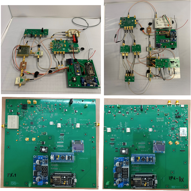
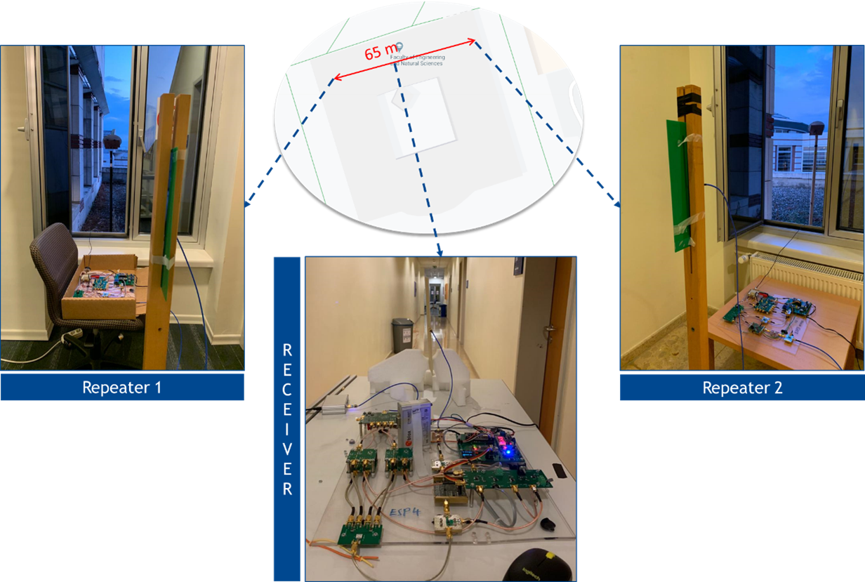
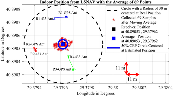
GPS Indoor Positioning
A novel indoor positioning system using Global Positioning System (GPS) signals in 433 MHz ISM band is designed in this project.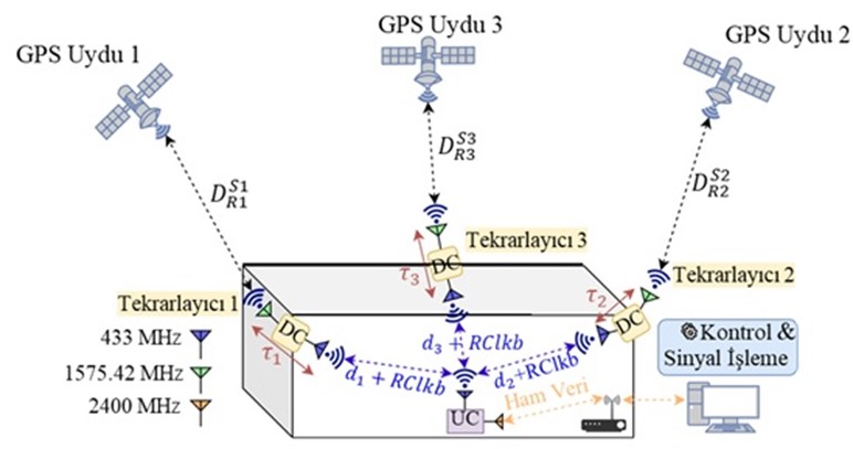
Automotive Radar System at 77GHz
In 77 GHZ band, there is a 5 GHz bandwidth allocated for application of short range automotive radar for the purposes of: stop and go, blind side detection, crash avoidance. This project involves on-chip antenna and active circuitry design at millimeter wave range. To realize our antennas and active circuitry, we use silicon based technology available at IHP microelectronic company, Germany. The most challenging part is the measurement process which requires high-tech devices and highly skilled operators. Some of our millimeter wave measurement setups are: W-band antenna measurement setup , W-band LNA gain and noise figure measurement setup , and our W- band Silicon Dielectric measurement setup .` Summary of our work and designs are as follow:
An Ultra-Wideband SiGe BiCMOS LNA for W-band Applications
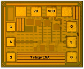 This paper presents the design steps and implementation of a W-band ultra-wideband LNA for both automotive and imaging applications. Three amplifiers based on common-emitter topology with different configurations are manufactured using IHP 0.13µm SiGe BiCMOS SG13G2 technology. A three-stage, single-ended structure is proposed for ultra-wideband imaging purposes. As the results are analyzed, this 0.2mm2 LNA can operate in a 25GHz of measured 3dB-bandwidth in W-band with 21dB peak gain and 4.9dB average noise figure using 1.5V supply voltage. It consumes 50mW of power in the edge operation conditions and the output 1dB compression point is found as -4dBm. To the best of the authors? knowledge, this chip achieves one of the best overall performances compared to other W-band LNAs.
E. Ozturk, M. Seyyedesfahlan, M. Kaynak and I. Tekin, “An Ultra-Wideband SiGe BiCMOS LNA for W-band Applications”, Microwave and Wireless Components Letters 2014 (in Review)
This paper presents the design steps and implementation of a W-band ultra-wideband LNA for both automotive and imaging applications. Three amplifiers based on common-emitter topology with different configurations are manufactured using IHP 0.13µm SiGe BiCMOS SG13G2 technology. A three-stage, single-ended structure is proposed for ultra-wideband imaging purposes. As the results are analyzed, this 0.2mm2 LNA can operate in a 25GHz of measured 3dB-bandwidth in W-band with 21dB peak gain and 4.9dB average noise figure using 1.5V supply voltage. It consumes 50mW of power in the edge operation conditions and the output 1dB compression point is found as -4dBm. To the best of the authors? knowledge, this chip achieves one of the best overall performances compared to other W-band LNAs.
E. Ozturk, M. Seyyedesfahlan, M. Kaynak and I. Tekin, “An Ultra-Wideband SiGe BiCMOS LNA for W-band Applications”, Microwave and Wireless Components Letters 2014 (in Review)
SiGe Process Integrated Full-360o MEMS Based Active Phase Shifter for W-band Automotive Radar
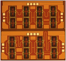
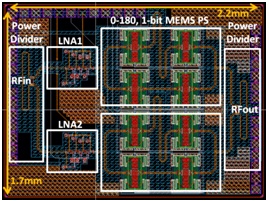 This paper presents the implementation of a MEMS based active phase shifter by using vector sum method. The proposed phase shifter comprises of two variable gain amplifiers (VGA), a Wilkinson Power divider with 90o phase shift lines, a Wilkinson power combiner and two 1-bit (0o/180o) MEMS phase shifters. First, all the components were designed and fabricated individually to check for their proper functionality, then they were brought together in a novel vector sum topology to work as a full 360o span phase shifter. Fabricated VGAs function properly at designed frequency (77GHz) with gain variation from 0 ? 14 dB with the tuned base voltages from 1.8 ? 2.3 V. The VGAs not only serve for providing the weighted amplitudes but also compensate 4.3 dB loss from 1-bit MEMS phase shifter and 0.8 dB loss from each power divider and combiner. Active/passive components and MEMS switches are all integrated at one single chip of 3.74 mm2 and manufactured with IHP 0.25 µm SiGe BiCMOS technology. As to our knowledge, this is the first demonstration of an active phase shifter using integrated active components and MEMS technology. Presented phase shifting mechanism can be used at automotive radar system for beam steering purpose.
E. Ozturk, M. H. Nemati, M. Kaynak, B. Tillack and I. Tekin, “SiGe Process Integrated Full 360 degree MEMS Based Active Phase Shifter for W-band Automotive Radar”, IET Microwaves, Antennas & Propagation 2014 (accepted)
This paper presents the implementation of a MEMS based active phase shifter by using vector sum method. The proposed phase shifter comprises of two variable gain amplifiers (VGA), a Wilkinson Power divider with 90o phase shift lines, a Wilkinson power combiner and two 1-bit (0o/180o) MEMS phase shifters. First, all the components were designed and fabricated individually to check for their proper functionality, then they were brought together in a novel vector sum topology to work as a full 360o span phase shifter. Fabricated VGAs function properly at designed frequency (77GHz) with gain variation from 0 ? 14 dB with the tuned base voltages from 1.8 ? 2.3 V. The VGAs not only serve for providing the weighted amplitudes but also compensate 4.3 dB loss from 1-bit MEMS phase shifter and 0.8 dB loss from each power divider and combiner. Active/passive components and MEMS switches are all integrated at one single chip of 3.74 mm2 and manufactured with IHP 0.25 µm SiGe BiCMOS technology. As to our knowledge, this is the first demonstration of an active phase shifter using integrated active components and MEMS technology. Presented phase shifting mechanism can be used at automotive radar system for beam steering purpose.
E. Ozturk, M. H. Nemati, M. Kaynak, B. Tillack and I. Tekin, “SiGe Process Integrated Full 360 degree MEMS Based Active Phase Shifter for W-band Automotive Radar”, IET Microwaves, Antennas & Propagation 2014 (accepted)
A Novel Three Vector Sum Active Phase Shifter Design for W-band Automotive Radar Applications
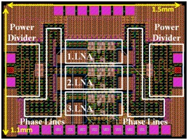 This paper presents a novel active W-band phase shifter implemented using IHP SiGe HBT 0.25µm SG25H1 technology with three vector (00-1200-2400) sum technique. The integrated chip consists of a 3-way Wilkinson power divider/combiner with 0o-120o-240o phase shifting lines and three low noise amplifiers (LNA) working at 77 GHz, which comprises a total of 1.5mm X 1.1mm die area. The phase shifting is based on the weighted sum of three vectors which have 120o angle separation so that all 360o could be scanned with simple amplitude control only. The LNAs are fabricated using IHP technology and can be used successfully in the active phase shifter design. LNA measurement results show that a variable gain of 0dB to 14dB at 77GHz can be obtained by sweeping the base voltage between 1.8V and 2.3V. The simulation results of complete system, including power dividers, phase shifting lines, LNAs, power combiners show that phase can be adjusted by 360 degrees with a maximum gain of 1.8 dB. Input/output return loss for all the possible phase states are below 15dB. The proposed phase shifter can be used in W-band applications for full scan of 360o.
E. Ozturk, and I. Tekin, “A Novel Three Vector Sum Active Phase Shifter Design for W-band Automotive Radar Applications”, Microwave and Optical Technology Letters 2014 (accepted)
This paper presents a novel active W-band phase shifter implemented using IHP SiGe HBT 0.25µm SG25H1 technology with three vector (00-1200-2400) sum technique. The integrated chip consists of a 3-way Wilkinson power divider/combiner with 0o-120o-240o phase shifting lines and three low noise amplifiers (LNA) working at 77 GHz, which comprises a total of 1.5mm X 1.1mm die area. The phase shifting is based on the weighted sum of three vectors which have 120o angle separation so that all 360o could be scanned with simple amplitude control only. The LNAs are fabricated using IHP technology and can be used successfully in the active phase shifter design. LNA measurement results show that a variable gain of 0dB to 14dB at 77GHz can be obtained by sweeping the base voltage between 1.8V and 2.3V. The simulation results of complete system, including power dividers, phase shifting lines, LNAs, power combiners show that phase can be adjusted by 360 degrees with a maximum gain of 1.8 dB. Input/output return loss for all the possible phase states are below 15dB. The proposed phase shifter can be used in W-band applications for full scan of 360o.
E. Ozturk, and I. Tekin, “A Novel Three Vector Sum Active Phase Shifter Design for W-band Automotive Radar Applications”, Microwave and Optical Technology Letters 2014 (accepted)
SiGe Integrated 2×2 Bit MEMS Based Digital Phase Shifter for 77GHz Automotive Radar Applications
 Two 2-bit MEMS digital phase shifters have been implemented using IHP?s MEMS switch embedded 0.25 µm SG25H1 SiGe BiCMOS technology for 77 GHz automotive radar applications. Each bit of the phase shifter is obtained by BiCMOS embedded low-loss RF-MEMS switching between microstrip transmission line sections of different lengths. Input/output impedances are matched below 10dB return loss with 8 GHz bandwidth. Maximum of 2o and 10o (RMS) phase error with insertion loss of 8.8 dB and 9.3 dB are measured at 77 GHz for 2 Least Significant Bit (LSB, 90o tune with 22.5o increments) and 2 Most Significant Bit (MSB, 360o tune with 90o increments) phase shifters, respectively, resulting in a chip 2mm x 0.9mm area each. As to our knowledge, this is the first SiGe process integrated MEMS phase shifter.
E. Ozturk, M. Kaynak, and I. Tekin, “SiGe Integrated 2×2 Bit MEMS Based Digital Phase Shifter for 77GHz Automotive Radar Applications”, Microwave and Wireless Components Letters 2014 (in Review)
Two 2-bit MEMS digital phase shifters have been implemented using IHP?s MEMS switch embedded 0.25 µm SG25H1 SiGe BiCMOS technology for 77 GHz automotive radar applications. Each bit of the phase shifter is obtained by BiCMOS embedded low-loss RF-MEMS switching between microstrip transmission line sections of different lengths. Input/output impedances are matched below 10dB return loss with 8 GHz bandwidth. Maximum of 2o and 10o (RMS) phase error with insertion loss of 8.8 dB and 9.3 dB are measured at 77 GHz for 2 Least Significant Bit (LSB, 90o tune with 22.5o increments) and 2 Most Significant Bit (MSB, 360o tune with 90o increments) phase shifters, respectively, resulting in a chip 2mm x 0.9mm area each. As to our knowledge, this is the first SiGe process integrated MEMS phase shifter.
E. Ozturk, M. Kaynak, and I. Tekin, “SiGe Integrated 2×2 Bit MEMS Based Digital Phase Shifter for 77GHz Automotive Radar Applications”, Microwave and Wireless Components Letters 2014 (in Review)
77 GHz On-Chip Dipole Type Antennas for Automotive Radar Applications
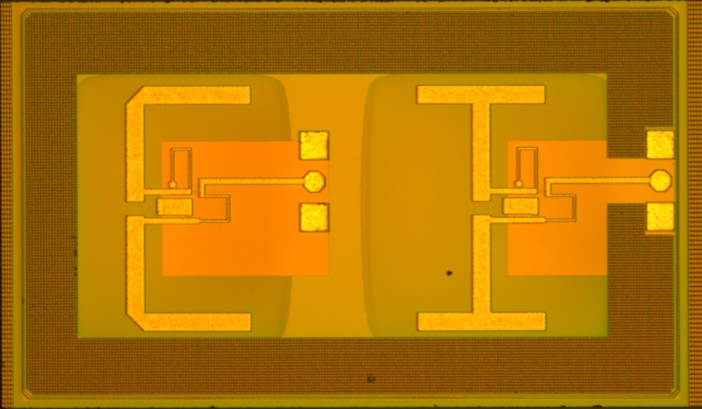 This work presents the design and implementation of flat, L-type and T-type 77 GHz on-chip strip dipole antennas integrated with a lumped LC balun circuit. The on-chip antennas and the balun circuit are realized by using IHP?s 0.25 ?m SiGe BiCMOS technology with a localized back-side etch (LBE) module to decrease substrate loss. The strip dipole antennas are fed by a lumped LC circuit balun integrated on the same substrate and occupies an area of smaller than 0.5 mm2; including the RF pads for the T-type dipole. For increased directivity, the etched Silicon substrate is placed on a metal ground plate. Experimental and simulation results show that antennas are well matched around 77 GHz band and achieve up to 7-12 GHz impedance bandwidth with the LC balun circuit. Simulated antenna gains range from 1 dBi to 3.6 dBi at 77 GHz. The compact size of the antennas and the feeding structure make it well suited for 77 GHz single chip automotive radar and array applications.
Mehdi Seyyed-Esfahlan, Mehmet Kaynak, and Ibrahim Tekin, “77 GHz On-Chip Dipole Type Antennas for Automotive Radar Applications“, AWPL, 2013, Accepted.
This work presents the design and implementation of flat, L-type and T-type 77 GHz on-chip strip dipole antennas integrated with a lumped LC balun circuit. The on-chip antennas and the balun circuit are realized by using IHP?s 0.25 ?m SiGe BiCMOS technology with a localized back-side etch (LBE) module to decrease substrate loss. The strip dipole antennas are fed by a lumped LC circuit balun integrated on the same substrate and occupies an area of smaller than 0.5 mm2; including the RF pads for the T-type dipole. For increased directivity, the etched Silicon substrate is placed on a metal ground plate. Experimental and simulation results show that antennas are well matched around 77 GHz band and achieve up to 7-12 GHz impedance bandwidth with the LC balun circuit. Simulated antenna gains range from 1 dBi to 3.6 dBi at 77 GHz. The compact size of the antennas and the feeding structure make it well suited for 77 GHz single chip automotive radar and array applications.
Mehdi Seyyed-Esfahlan, Mehmet Kaynak, and Ibrahim Tekin, “77 GHz On-Chip Dipole Type Antennas for Automotive Radar Applications“, AWPL, 2013, Accepted.
77GHz on-chip Microstrip patch antenna with suppressed surface wave using EBG substrate
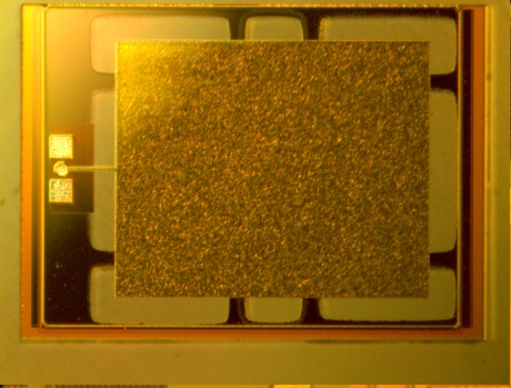 This work presents the design of a patch antenna with suppressed surface waves by means of applying an electromagnetic band-gap structure. Establishing the antenna on high dielectric substrate such as Silicon makes it possible to integrate the antenna with RFIC active component and circuitry. However, the performance (gain and radiation pattern) of antenna will be degraded due to the presence of surface waves on a thick dielectric substrate. It is possible to design an engineered substrate that filters out the surface wave around the frequency of interest. Moreover, having high dielectric substrate will localize EM wave to substrate and hence reduce antenna gain. For this problem, available silicon etching technology is used to remove the substrate right under the patch and have a locally low dielectric constant substrate underneath the antenna. Proposed microstrip antenna resonates at 77GHz with 7dB realized gain which can be used in array for Automotive Radar purposes. Simulation results show great improvement in radiation pattern and 3dB increase in antenna’s broadside gain in comparison with antenna on normal substrate.
M.H.Nemati, and Ibrahim Tekin, ?A 77GHz on-chip Microstrip patch antenna with suppressed surface wave using EBG substrate,? IEEE International Symposium on Antennas and Propagation, Orlando, July 2013.
This work presents the design of a patch antenna with suppressed surface waves by means of applying an electromagnetic band-gap structure. Establishing the antenna on high dielectric substrate such as Silicon makes it possible to integrate the antenna with RFIC active component and circuitry. However, the performance (gain and radiation pattern) of antenna will be degraded due to the presence of surface waves on a thick dielectric substrate. It is possible to design an engineered substrate that filters out the surface wave around the frequency of interest. Moreover, having high dielectric substrate will localize EM wave to substrate and hence reduce antenna gain. For this problem, available silicon etching technology is used to remove the substrate right under the patch and have a locally low dielectric constant substrate underneath the antenna. Proposed microstrip antenna resonates at 77GHz with 7dB realized gain which can be used in array for Automotive Radar purposes. Simulation results show great improvement in radiation pattern and 3dB increase in antenna’s broadside gain in comparison with antenna on normal substrate.
M.H.Nemati, and Ibrahim Tekin, ?A 77GHz on-chip Microstrip patch antenna with suppressed surface wave using EBG substrate,? IEEE International Symposium on Antennas and Propagation, Orlando, July 2013.
FMCW Radar at 1GHz
Nowadays radar systems have many civil and commercial applications. FMCW(Frequency Modulated Continuous Wave) are among popular radar systems. FMCW radar can measure range and velocity(Doppler effect) at the same time. Our designed FMCW radar works at 1GHz and is able to detect object with range up to 100meter and velocity up to 300km/h. For detailed information see sa-antenrf-fmcw-radar.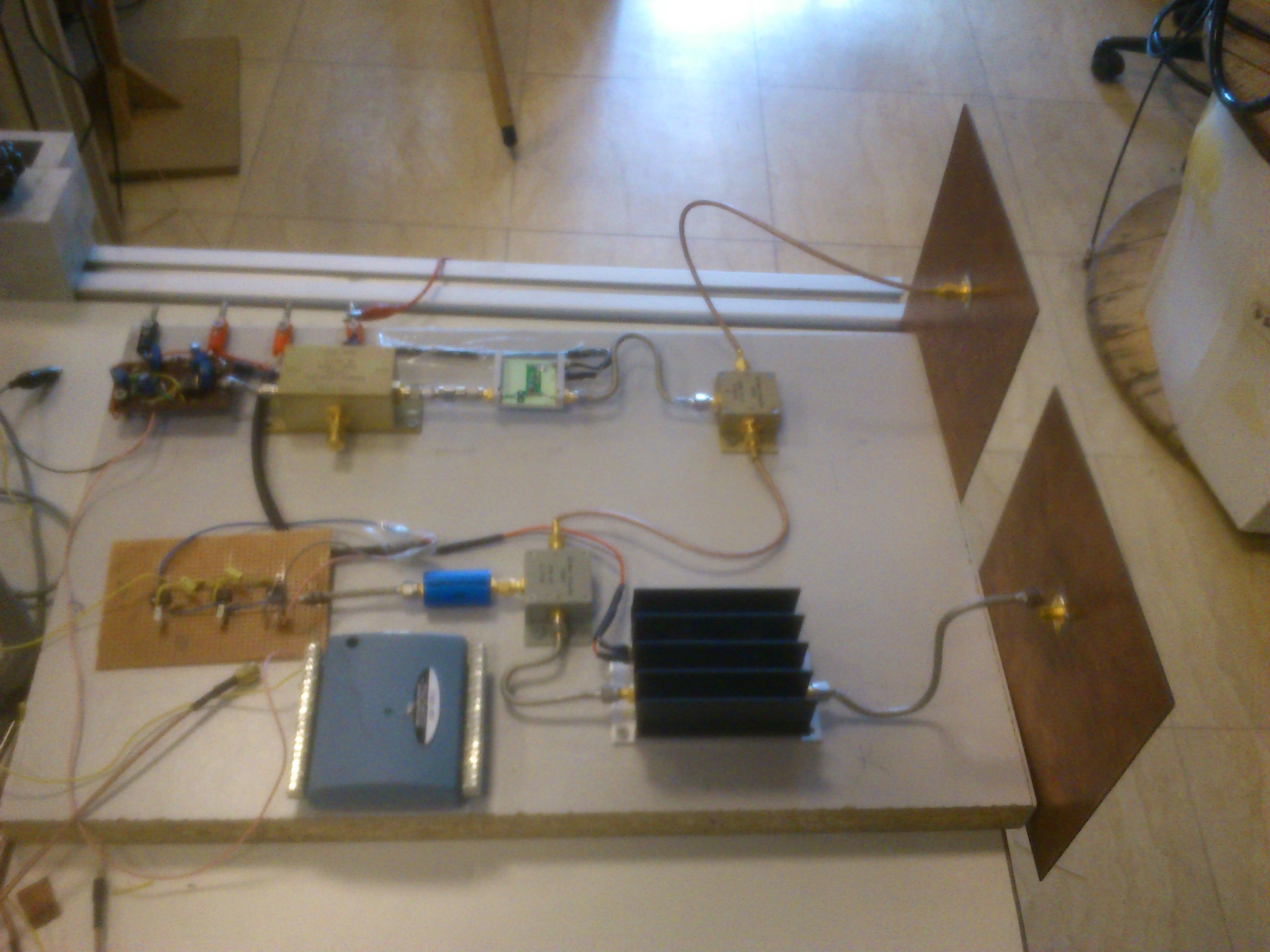
Indoor GPS positioning system
For today’s typical wireless sensor technology, DC power consumption should be very low.The ultra low power systems are ideal for systems running on scavenged power or for ?install and forget’ sensor systems for long-term monitoring. This includes body area networks (BANs), ?go-anywhere’ health and comfort monitoring, industrial control and predictive maintenance.We are working on some wireless applications using ultra low RF devices. The objective to use such low power devices is to extend the functionality and autonomy of wireless sensor networks.Curently we are investigating Value Line Transceivers from Texas Instruments(TI) for such applications.Specially we are working on CC110L from TI for indoor GPS applications and low data rate telemetry purposes. We are using Smart RF Studio for CC110L evaluation.This software is used for CC110L configuration(Transmit or receive mode etc), to measure received signal strength and packet error rate.SmartRF Studio communicate with the Evaluation Board over the USB interface.The Application programming interface (API) is provided by the CEBAL library.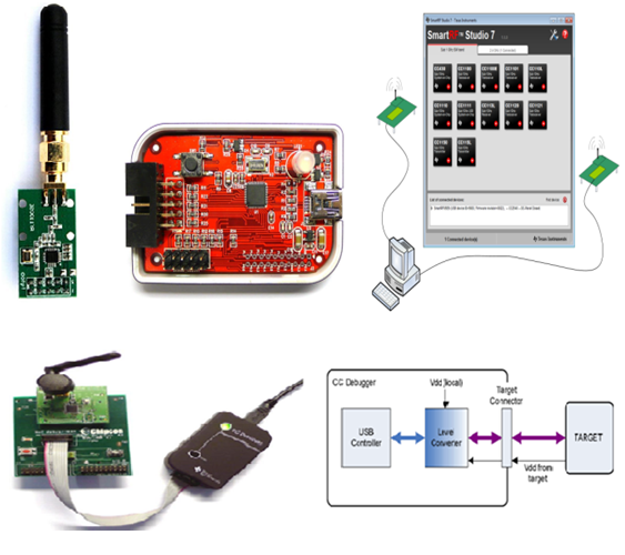
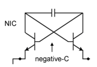
Non-Foster Matching at 2GHz:
Current smart phones have many communication/location systems such as GSM/3G/WLAN/Bluetooth/GPS/Glonass implemented as hardware. The number of antennas required for these systems are increasing and they also have to be implemented within a limited area; which will make electrically small antennas play a very significant role. Currently, electrically small antennas are used for some applications with degraded performance. Matching of these small radiating antennas is achieved by non-foster matching circuits which are discrete implementation of active circuits such as amplifiers/oscillators. In our contribution, we will integrate both the antenna and the active circuit, which achieves matching, in integrated process provided by IHP. It is beyond the state-of-art since the antenna will be very small to be cost effective and also integration will be also very cost-effective since both the antenna and the active circuits will be manufactured using the same RFIC process. This will improve the performance as well as generating compact transceivers. In this work we have studied the viability of designing Negative Impedance Converter (NIC) at microwave frequency say around 2GHz. surfing on open literature, 1.5GHz is the highest frequency in which NIC design has been reported to date. More information nic-report-ieee-format